What's Included
- Display Console
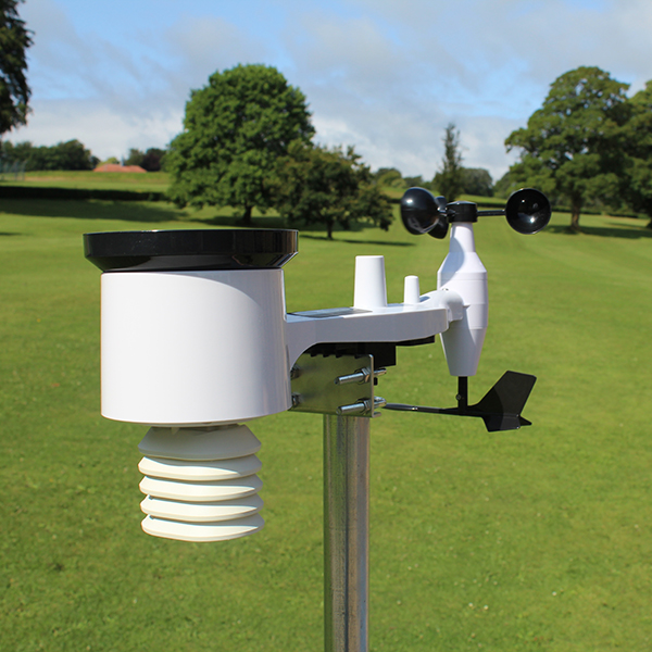
- Outdoor Sensor Body
- Wind Speed Cups
- Wind Vane
- Mounting Kit
- 2 x U-Bolts
- 4 x Threaded M5 nuts for U-Bolts
- Metal Mounting Plate
- 30cm Mounting Pole
- M5 Wrench
- Ac Adapter
*Batteries not included
Important Information
To complete assembly you will need a Philips screwdriver (size PH0) and a wrench (size M5; included with the weather station).
Note
We suggest you assemble all components of the IoT weather station, including the console in one location so you can easily test functionality. After testing, place the outdoor the outdoor sensor package in the desired location. Note, however, movement during assembly, and after assembly can cause the rain sensor to falsely detect rain. This is unavoidable but something to note.
Attention
Follow the suggested order for battery installation (outdoor sensorfirst, console ssecond)
Ensure batteries are installed with coorrect polarity (+/-)
Do not mix old and new batteries
Do not use rechargable batteries
If outdoor temperature may go below 0 degrees celcius for prolonged periods, Lithium based batteries are suggested over alkaline types for the outdoor sensor component.
Outdoor Sensor Package Assembly
See figure 1 to locate and understand all the parts of the outdoor sensor package once fully assembled.
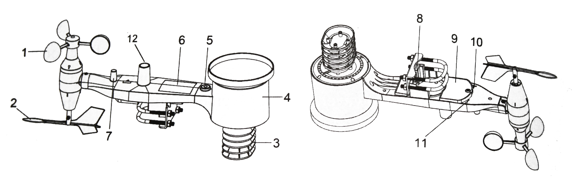
Figure 1
1 – Wind Speed Cups
2 – Wind Vane
3 – Temperature and Humidity Sensors
4 – Rain Collector
5 – Bubble Level
6 – Solar Panel
7 – Antenna
8 – U-Bolts
9 – Battery Comartment Door
10 – Reset Button
12 – Light Sensor and UV Sensor
11 – LED (red) to Indicate Data Transmission
Figure 2
Install U-Bolts and Metal Plate
Installation of the U-bolts, which in turn are used to mount the sensor package on the mounting pole, require fixing to the metal mounting plate. The metal plate visible in figure 3, has four holes through which the ends of the two U-bolts will fit. The plate itself is inserted in a groove on the bottom of the unit (opposite side of the solar panel). Note, one side of the plate has a straight edge (which inserts into the groove), the other side is bent at a 90-degree angle and has a curved profile (which will end hugging the mounting pole). Once the metal plate is inserted, remove nuts from the U-bolts and insert both U-bolts through the respective holes of the metal plate as shown in figure 3.
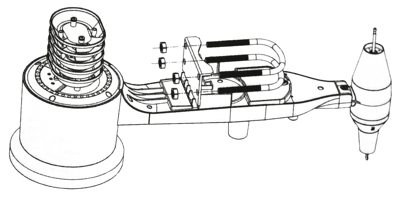
Figure 3
Loosely screw the nuts onto the end of the U-bolts. You will tighten these later during the final mounting. Final assembly is shown in figure 4.

Figure 4
Install the Wind Vane
Push the wind vane onto the shaft on the bottom side of the sensor package, until it goes no further, as shown in the left illustration of figure 5. Next, tighten the set screw, with a Philips screwdriver (size PH0), as shown in the right illustration, until the wind vane cannot be removed from the axle. Make sure the wind vane can rotate freely. The wind vane’s movement has a small amount of friction, which is helpful in providing steady wind direction measurements.
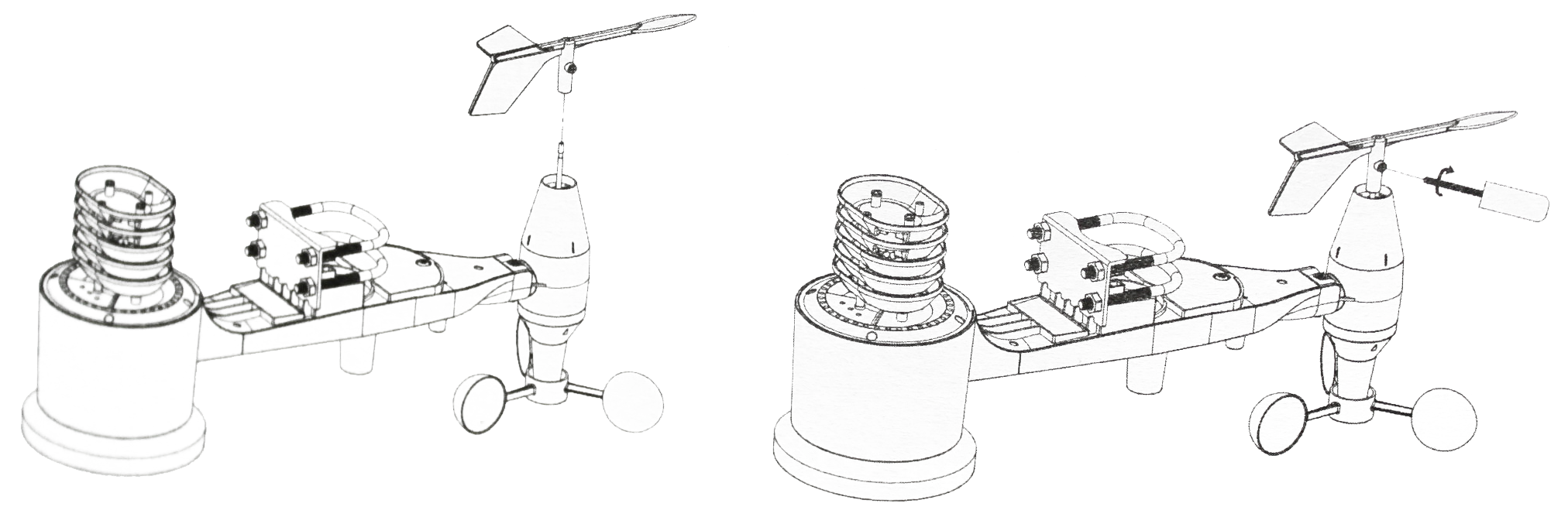
Figure 5
Install the Wind Speed Cups
Push the wind speed cup assembly onto the shaft as shown in figure 6. Tighten the set screw, with a Philips screwdriver (size PH0), as shown in the right illustration of figure 6. Make sure the cup assembly can rotate freely. There should be noticeable friction when it is turning.
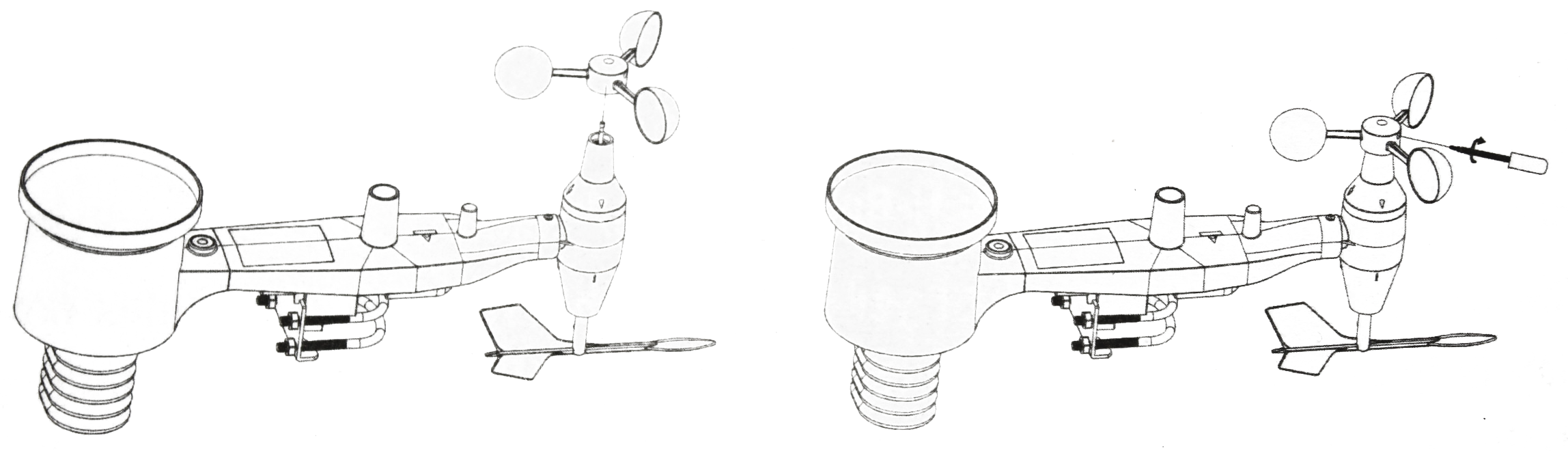
Figure 6
Install Batteries in the Sensor Package
Open the battery compartment with a screwdriver and insert 2 AA batteries into the battery compartment. Ensure correct polarity (+/-). The LED indicator on the back of the sensor package (item 11) will turn on for four seconds then flash once every 16 seconds indicating sensor data transmission. If you missed the initial indication you can remove the batteries and start over.
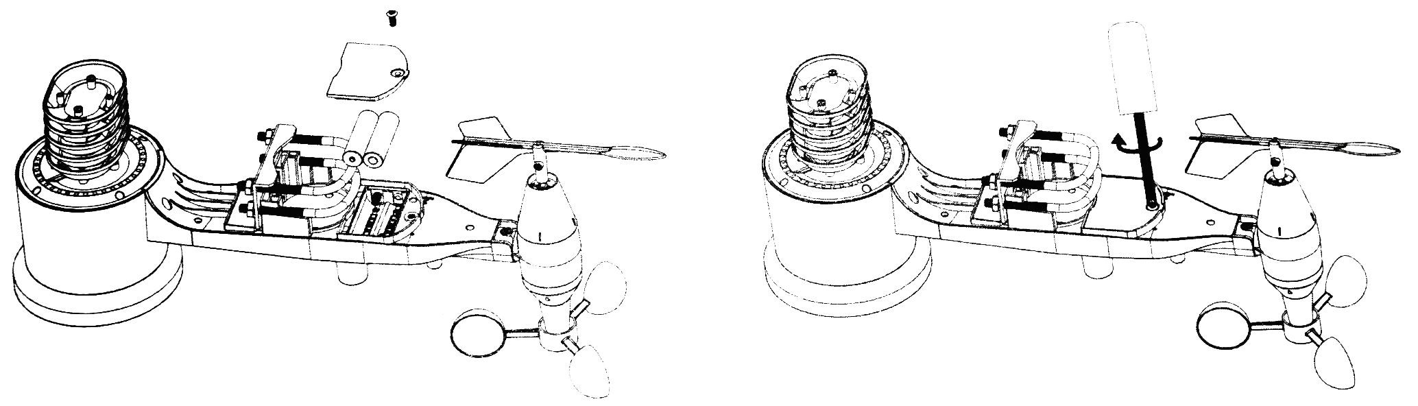
Figure 7
Note
If the LED does not light up. or is on permanently, make sure the battery is inserted the correct way and inserted fully. Do not install the batteries backwards as this may permanently damage the outdoor sensor.
Connecting to a Wi-Fi Network
*Mobile device or tablet required
With the outdoor sensor package assembled now is the time to connect to a Wi-Fi network. To do this you will require the display console and power adapter.
Firstly, connect the display console to mains power using the power adapter supplied. You will see the data readings from the display console sensor as well as the data transmitted from the outdoor sensor package. If this is not the case return to ‘Outdoor Sensor Package Assembly‘ for troubleshooting.
Next, you will need to download the ‘WS View’ from the iOS or Google Paly app store. This will require your mobile device or tablet to do so.
Once downloaded, open the app. If this is your first time using the app you will be asked to enable location settings. You must do this.
Once enabled, you will be greeted with a screen showing multiple device options. The option you require is the one that resembles your display console. See figure 8. Select this options and click the ‘next’ button the the top right corner of the screen.
The next screen contains an image of your display console as well as some instructions for enabling the Wi-Fi configuration mode on your display console. See figure 9. Follow these instructions and then select the ‘next’ button in the top right corner of the app screen.
The app will now search for the display console. During this process it will the app will go through multiple steps as shown in figure 10 before finally stating ‘setup is complete, ready to verify’.
Figure 8
Figure 9
Figure 10
With the outdoor sensor package assembled now is the time to connect to a Wi-Fi network. To do this you will require the display console and power adapter.
Firstly, connect the display console to mains power using the power adapter supplied. You will see the data readings from the display console sensor as well as the data transmitted from the outdoor sensor package. If this is not the case return to ‘Outdoor Sensor Package Assembly‘ for troubleshooting.
Next, you will need to download the ‘WS View’ from the iOS or Google Paly app store. This will require your mobile device or tablet to do so.
Once downloaded, open the app. If this is your first time using the app you will be asked to enable location settings. You must do this.
Once enabled, you will be greeted with a screen showing multiple device options. The option you require is the one that resembles your display console. See figure 8. Select this options and click the ‘next’ button the the top right corner of the screen.
Figure 8
Figure 9
Figure 10
The next screen contains an image of your display console as well as some instructions for enabling the Wi-Fi configuration mode on your display console. See figure 9. Follow these instructions and then select the ‘next’ button in the top right corner of the app screen.
The app will now search for the display console. During this process it will the app will go through multiple steps as shown in figure 10 before finally stating ‘setup is complete, ready to verify’.
Figure 11
Figure 12
The app then diverts to the screen which allows you to connect the display console to your network. See figure 11.
Begin by inserting your Wi-Fi network’s SSID into the field labelled SSID. Alternatively you can use the scan feature to search for Wi-Fi networks automatically. (Note: SSID is sometimes known as Wi-Fi name).
Next, insert your Wi-Fi password into the password field.
The MAC address of the device can be found at the bottom of the screen as shown in figure 11.
The section below called ‘ecowitt.net’ must be set to off as shown in figure 11.
Scroll down the app screen until you find the ‘Customized’ section. See figure 12 This section is where the display unit is connected to the IoT Exploratory ecosystem.
The following steps are illustrated in figure 12.
Select ‘Enable’ and ‘Wunderground’ options.
In the Server IP / Hostname field enter, www.ws.sciencescope.uk
In the Path field enter, /weatherstation/updateweatherstation.php?
In the Station ID field enter the device ID of your weather station. This can be found on the box of your weather station. The device ID will begin with MB. The device ID in figure 12 is an example and will not be the correct device ID for your weather station.
In the Station Key field enter your weather station’s device ID again.
The app then diverts to the screen which allows you to connect the display console to your network. See figure 11.
Begin by inserting your Wi-Fi network’s SSID into the field labelled SSID. Alternatively you can use the scan feature to search for Wi-Fi networks automatically. (Note: SSID is sometimes known as Wi-Fi name).
Next, insert your Wi-Fi password into the password field.
The section below called ‘ecowitt.net’ must be set to off as shown in figure 11.
Scroll down the app screen until you find the ‘Customized’ section. See figure 12 This section is where the display unit is connected to the IoT Exploratory ecosystem.
The following steps are illustrated in figure 12.
Select ‘Enable’ and ‘Wunderground’ options.
In the Server IP / Hostname field enter, www.ws.sciencescope.uk
In the Path field enter, /weatherstation/updateweatherstation.php?
In the Station ID field enter the device ID of your weather station. This can be found on the box of your weather station. The device ID will begin with MB. The device ID in figure 12 is an example and will not be the correct device ID for your weather station.
In the Station Key field enter your weather station’s device ID again.
In the Port field enter 80.
In the Upload Interval field enter 300.
Finally, select the save button at the bottom of the app screen.
Figure 11
Figure 12
In the Port field enter 80.
In the Upload Interval field enter 300.
Finally, select the save button at the bottom of the app screen.
You will be diverted to an app screen showing your connected devices. See figure 13.
Your display console will now be connected to your Wi-Fi network and will begin sending data to the IoT Exploratory tool.
Find your Weather Station Data in the IoT Exploratory
Go to the IoT Exploratory tool in the menu bar at the top of this page and open it in a new tab.
All IoT devices in the IoT Exploratory ecosystem have a unique device ID that identifies them. This device ID is located on your weather station box. In the IoT Exploratory tool you can find your device in the devices list using this device ID.
Note: You will need to wait a minimum of 15 minutes to allow your IoT weather station to send its first data point to the IoT Exploratory. If after 30 minutes your weather station has not appeared in the Exploratory tool repeat the ‘Connecting to a Wi-Fi Network’ steps. If the device still does not register please contact us for support.
To understand how to build data sets and analyse the data from your IoT device and others, see the Getting Started guide.
Figure 13
You will be diverted to an app screen showing your connected devices. See figure 13.
Your display console will now be connected to your Wi-Fi network and will begin sending data to the IoT Exploratory tool.
Figure 13
Find your Weather Station Data in the IoT Exploratory
Go to the IoT Exploratory tool in the menu bar at the top of this page and open it in a new tab.
All IoT devices in the IoT Exploratory ecosystem have a unique device ID that identifies them. This device ID is located on your weather station box. In the IoT Exploratory tool you can find your device in the devices list using this device ID.
Note: You will need to wait a minimum of 15 minutes to allow your IoT weather station to send its first data point to the IoT Exploratory. If after 30 minutes your weather station has not appeared in the Exploratory tool repeat the ‘Connecting to a Wi-Fi Network’ steps. If the device still does not register please contact us for support.
To understand how to build data sets and analyse the data from your IoT device and others, see the Getting Started guide.
Mounting the Weather Station
*For this stage you will require the metal mounting pole and M5 wrench included in the weather station package. Further mounting supports may be required.
Outdoor Sensor Package Mounting Location
There are a number of location options for the outdoor sensor package. On the roof of a building, in an open space, on a garden building or structure and others. The most reliable location for mounting is on a roof or above the roof line of a building. This ensures accurate weather data which is representative of the surroundings is collected by the weather station. This is not always possible however.
It may be the case surrounding objects and buildings are higher than the location options for the weather station. If this is the case, a 4:1 ratio should be applied as illustrated in figure 14.
For example, you wish to locate the outdoor sensor package in a garden and there is a tree nearby, 6 meters above the height of the outdoor sensor package. You should aim to locate the outdoor sensor package a minimum of 24 meters away from the tree.
This is one example, however applying the 4:1 ratio to other locations will ensure accurate and representative data is collected.
If this is not possible, Aim to be as close to the 4:1 ratio as possible.

Figure 14
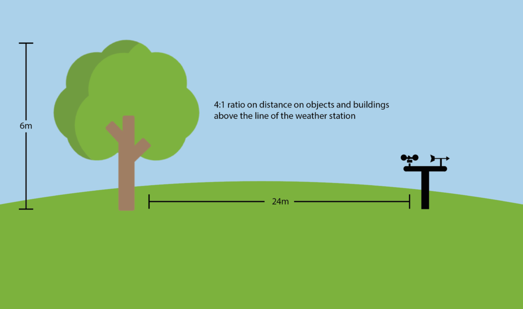
Figure 14
The second point to note when choosing a location for the outdoor sensor package is how far it is away from the display console, located indoors. The display console is rated to function at 80 meters line of sight (under ideal circumstances of no interference, barriers or walls). In most real-world scenarios, accounting for 1 or 2 walls, the line of site range is around 30 – 40 meters. Figure 15 outlines how different mediums effect the signal strength and therefore line of site distance.
Medium
Line of Sight Signal Strength Reduction
Glass (untreated)
5-15%
Plastics
10-15%
Wood
10-40%
Brick
10-40%
Concreate
40-80%
Metal
80-100%
Figure 15
Mounting Preparation
By this stage the outdoor sensor package should be connected to your Wi-Fi network and you will have chosen a location for mounting. It is now time to prepare the outdoor sensor package for mounting.
When performing the following steps do your best to keep the outdoor sensor unit as still as possible. This will minimise any unwanted data spikes of rain data.
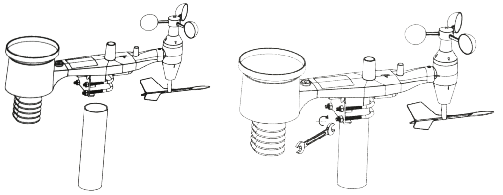
Figure 16
Begin by loosen the nuts on the 2 U-Bolts enough to allow the mounting pole to insert in between as illustrated in figure 16. Ensure they are still fastened.
Once loosened insert the mounting pole through the U-bolts until it comes into contact with the underside of the outdoor sensor package.
Hand tighten each of the 4 nuts, taking care to do so evenly. Do not use the wrench yet.
Mounting
Take the outdoor sensor package to your mounting location and attach the mounting pole securely to your mounting set up. (This set up is the responsibility and liability of the user and should be done by a person with adequate building skills).
Next, the outdoor sensor package must be orientated correctly and made level. Locate the arrow labelled “WEST” on top of the sensor package. This arrow should point due west. You will then require the wrench to begin tightening the nuts whilst ensuring the outdoor sensor package is level. The bubble level located on top of the sensor package will assist with this process. The bubble should be fully inside the red circle on the bubble level.
Your weather station is now mounted and ready for use with the Exploratory tool.
Keep in Touch
Keep up to date with new IoT Exploratory features and devices, training sessions, other news and events.
